
The Sanderson Group Webpages
Department of Chemistry
Durham University, Durham, UK
Optical Entrapment (Laser Tweezing)
Principle
The phenomenon of laser tweezing relies on a difference in refractive index between an object (ie. particle, typically 1-2 microns in diameter) and the medium surrounding it. When the particle is placed at the focal point of a beam of incident laser light in a confocal microscope, some of the light is deflected (ie. refracted) as it passes though the particle and the rest is reflected. The photons of the refracted light emerge from the particle with a different momentum from those incident on the particle due to the change in direction, and this creates a net force on the particle that 'pulls' it towards the objective lens. The reflected light on the other hand creates a force that 'pushes' the particle in the opposite direction from the pulling force due to the refracted light. The net effect of the two forces is a trapping force that holds the particle in the focus of the laser beam.
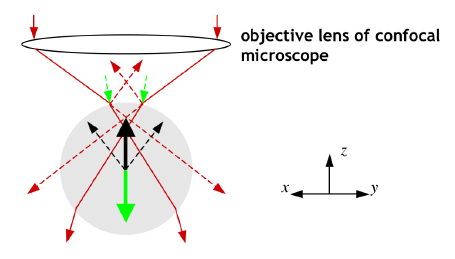
Figure 1
A simple diagram to show the
principles behind laser tweezing.
Forces due to reflected light are indicated in green. Forces due to
refracted light are indicated in black.
The photons of the refracted light emerge from the
particle with a different momentum from those incident on the
particle due to the change in direction, and this creates a net
(‘gradient’) force on the particle that acts in the z direction towards the objective
lens. The reflected light on the other hand creates a (‘scattering’)
force acts in the z direction
in the opposite sense to the gradient force. The net effect of the two
forces is a trapping force that holds the particle in the focus of the
laser beam. If the particle moves away from the z axis in the x-y plane, the net gradient force
acts to move the particle back towards the z axis.
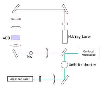
Typical Setup
The experimental setup used for tweezing multiple liposomes is outlined below:
Some movies showing trapping of liposomes are available here
In order to trap liposomes,
a solid-state Nd:YAG microwave laser is used as the source of the
trapping beam. This is passed through a series of mirrors and lenses to
condition the beam. One of the most important of these is the AOD
device, which is able to move the focus of the laser
precisely and rapidly rapidly between a number of different loci. This
enables multiple particles to be trapped, providing that the diffusion
coefficient of each particle is significantly longer than the time
taken to switch between the different loci, which is usually the case. An
Ar-ion laser is used as the light source for excitation of fluorescent
markers, with a Uniblitz shutter included in order to allow the
excitation to be pulsed (in order to reduce photobleaching).
The whole apparatus is mounted on an air table to minimise disruption
from vibrations.
Raman Tweezing
The basic Raman tweezers
apparatus (Figure 3) as a little simpler than that required for trapping multiple
particles, and uses a cw Argon ion laser of wavelength 514.5 nm and maximum power 2 W. The beam is passed through
two sets of expansion optics (L1 to L4), reflected from a 33:67
beamsplitter and directed into the microscope. Here, a dichroic mirror
is used to reflect the beam through the objective lens (x63) where the
optical trap is formed. For trapping and
acquisition of Raman spectra the laser is attenuated to a power of 12
mW, measured at the entrance aperture of the objective lens.
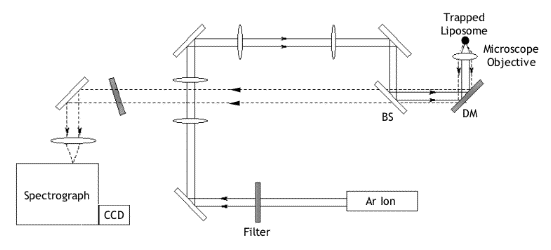
Figure 3 A simplified diagram showing the basic experimental setup for laser tweezing of liposomes to enable observation of Raman scattering
The Raman light scattered from the focal point is collimated by the objective lens and passed back along the same optical pathway. A holographic notch filter is used to transmit only the Raman shifted light above 514.5 nm. The beam is then focussed on to the entrance slit of the spectrometer and detector. To allow observation of the trapped liposome, filtered light (>700 nm) from the microscope is used to image the particle onto a CCD camera.